
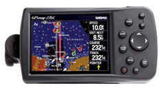
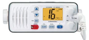
Although several projects on this website have NMEA-0183 connection examples, it has come to my attention that some readers would like more in-depth instructions on how this is done. One of the most popular NMEA-0183 connections is between a DSC enabled VHF radio and a chartplotter. In this tutorial, I will be using a popular small GPS chartplotter – a Garmin GPSMAP 276C, and connect it to an equally popular Icom IC-M304 DSC VHF radio.
The purpose of the NMEA-0183 connection is to provide position information to the DSC (emergency) function of the VHF radio, in the form of GPS LAT/LON from the chartplotter. In an emergency or other DSC function, the boat’s GPS position could be transmitted by the VHF radio, which would aid rescuers (emergency) or buddies (if they had similarly equipped systems) to locate you.
More advanced DSC systems cannot only transmit your position, they can also directly plot DSC signals you receiver directly on your chartplotter. This would require both VHF receiver and chartplotter to support this function. However, neither the GPSMAP 276C or IC-M304 support this function. Therefore, this is a basic system. If you would like to consider a more advanced system, check out my project in the Navigation section of this webpage for a system that does support this function.
I also chose the GPSMAP 276C for the example as it has an unconventional connection scheme, interconnecting NMEA-0183 data not only with a VHF receiver, but also with an optional depth sounder, and I’ll show both connection schemes.
Before continuing, a short familarization with NMEA-0183 is in order. NMEA-0183 is a point-to-point connection scheme that is used to interconnect navigation equipment. Any device that supports MMEA-0183 “should” be capable of communicating with other NMEA-0183 devices.
A NMEA-0183 connection consists of one transmitter (called a Talker in NMEA lingo) and one receiver (called a Listener). This establishes a NMEA channel. Data is sent by the Talker to the Listener as required, and both pieces of equipment have an established ONE-WAY connection. In a one-way connection, data can only flow in one direction – from the talker equipment to the listener equipment. This is indeed sufficient for many devices, including the basic chartplotter-to-VHF radio example herein. The chartplotter is the Talker; sending GPS data to the VHF radio, which is the listener. There is no reason for the VHF radio to communicate with the chartplotter.
But what if there was? If a TWO-WAY connection is required, then the VHF radio and Chartplotter would both need a TALKER and LISTENER port. If this existed, simply connect each TALKER to each LISTENER, and two-way communication would be established.
Finally, in some situations, the GPS data from the chartplotter may have to be sent to multiple devices. Fortunately, a TALKER can generally be paralleled to up to four different LISTENERS. But what if several devices needed to send data to the GPS’s LISTENER. Unfortunately, this is not possible as only a LISTENER can only be connected to one TALKER. Again, one TALKER can be connected to up to four LISTENERS, but only a LISTENER can only hear one TALKER. Of course, if the GPS had more than one LISTENER channel, it could listen to one TALKER on each channel. And advanced devices, such as multiplexers could be used, but that is beyond the scope of this tutorial. For further information on advanced NMEA-0183 topics, see my NMEA-0183 Primer.
Upon consulting the product documentation, we find that the NMEA-0183 connection for the radio to be rather straightforward, but for the chartplotter, its really a mess. However, create your own chart showing the various required connections. You should end up with something like I have shown below:
| Garmin GPSMAP276C | ICOM IC-M304 | |||
| Wire | Function | Wire | Function | |
| RED | = 12VDC unit power | YELLOW | = NMEA + IN | |
| BLACK | = Ground | GREEN | = NMEA – IN | |
| BLUE | = Data Out | |||
| YELLOW | = Data In | |||
Next, create yourself a schematic diagram of the connection. Notice that the Garmin Chartplotter uses GROUND for not only the power ground to the chartplotter, but also the lowside (-) connection for both NMEA IN and NMEA OUT.
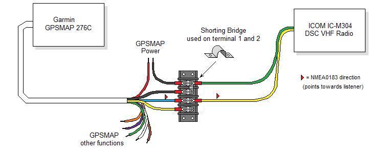
What makes this connection a bit complicated is the GPSMAP 276C uses the ground cable for both system ground, and signal grounds for the NMEA connections. I find that when interconnecting systems, a terminal strip is very useful, and I prefer it over simply wrapping the splice with tape. Note also that I used a shorting bridge on the two top terminals, which connects all 4 of the lugs together at ground. This is preferable than doubling up on the terminals. However, doubling up is sometimes necessary, and can be done – if you never use more than TWO terminals on any one connector.
The other wires are not shown as they do not concern themselves with the NMEA-0183 connection. Consult the documentation for proper connection of the power wires as well as other functions. The power wires for the GPSMAP 276C is shown only to clarify the common ground connection for that unit
Lastly, refer to the little red arrows. They indicate the NMEA-0183 data flow, i.e. data flowing from TALKER to LISTENER. In the above diagram, note that NMEA-0283 data flows from the GPSMAP 276C (TALKER) to the M304 (LISTENER). This provides GPS data to the VHF Radio, which is what we want.
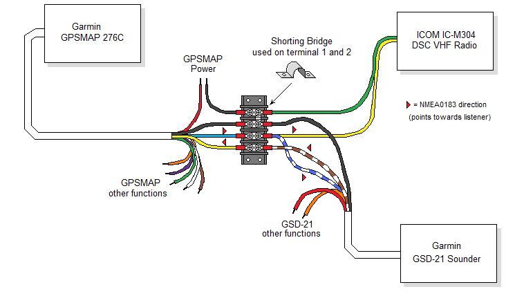
In the second setp, we asdded an optional sounder to the system, a Garmin GSD-21. This sounder is capable of both NMEA-0183 and NMEA-2000 modes of operation, however since this tutorial is about NMEA-0183, we are limiting our discussion to this connection. Again, Garmin uses a common negative wire for both power and network, so there is only one wire for NMEA IN and one for NMEA OUT.
Note that the GPS TALKER (NMEA OUT) connection is paralleled to the LISTNER (NMEA IN) connection on both GSD-21 and the VHF radio. If you recall, this is permissible as one TALKER can be connected to up to four LISTENERS. Since the VHF radio does not have a TALKER, the GSD-21’s TALKER is connected to the GPS LISTENER. Refer to the arrow directions to determine where the TALKERs and LISTENERs are.
The example above was certainly not typical. I used it to show the complexity you may encounter in a real world situation with popular equipment. However, more typical connections are shown below. I have shown both a LISTENER only and a LISTENER/TALKER setup. The TALKER setup would be the one that would plot the received DSC position on a charplotter. Also I have shown both shielded and unshielded wire. These are actual examples of what you may likely find.
Contents
Color Code
While the NMEA-0183 standard does have an official color code, it is often not followed by manufacturers – as shown by the real-world examples below. Always consult the manufacturer’s data for the color code used before making any interconnects.
| Name | Color | Function |
| Talker A | White | Data High |
| Talker B | Brown | Data Low |
| Listener A | Yellow | Data High |
| Listener B | Green | Data Low |
In practice, you may wish to install the terminal board into a waterproof enclosure, such as a NEMA-4x enclosure. Refer to Constructing waterproof electronic and electrical boxes on the website.
NMEA-0183 Sentence Compatibility.
Even though we now have a good NMEA-0183 network connection between our GPS Chartplotter and VHF radio, this does not ensure everything will work. We also have to make sure each system understands each other. Each time a NMEA-0183 TALKER sends data, it is called a “sentence”. The sentences are defined by the NMEA standard, so that equipment can communicate. In addition, each manufacturer is allowed private sentences; those which are unique to the brand, and other manufacturer’s equipment will not understand. The private sentences are typically used for unique functions within one brand’s equipment.
Again, we need to refer to the manufacturer’s data to see what sentences it outputs via it’s TALKER, as well as sentences it receives by it’s LISTENER it can understand.
| Garmin GPSMAP276C | ICOM IC-M304 | |||
| Output sentence | Description | Input sentence | Description | |
| GPRMC | = Minimum Navigation Information | RMC | = Minimum Navigation Information | |
| GPGGA | = GPS Fix Data | GGA | = GPS Fix Data | |
| GPGSA | = GPS Active Satellites | GNS | = GNSS Fix Data | |
| GPGSV | = Satellites in View | GLL | = Geographic Position (Lat/Lon) | |
| GPGLL | = Geographic Position (Lat/Lon) | |||
| GPBOD | = Bearing (waypoint to waypoint) | |||
| GPRTE | = Routes | |||
| GPWPL | = Waypoint Location | |||
| PGRME | = Estimated Error Information | |||
| PGRMZ | = Altitude | |||
| PGRMM | = Map Datum | |||
You can see that the Garmin GPS outputs many more sentences than is understood or required by the VHF receiver. Any sentences not understood are simply discarded. Note however, that there is one slight incompatibiity in that the receiver understands GNS, however, the GPS does not output it. GNS is obsolete and not defined in the latest versions of NMEA-0183. Luckily, the good news is the primary data required by the VHF receiver for DSC support is GLL, which is the lat/lon information.
MMSI
While not part of NMEA-0183, any discussion on a DSC VHF radio installation would not be complete without discussing MMSI (Maritime Mobile Service Identity), which is a real fancy name for a phone number. For the DSC system to work properly, each VHF radio must have a unique identifier to distinguish it from all other systems. This unique identifier is a MMSI. Essentially, you must apply for a MMSI number, then configure your VHF radio by typing that number into its non-violatle memory.
Thankfully, obtaining a MMSI number is free for recreational boaters from Boat/US MMSI Registration. In addition to the MMSI, an on-line database exists that associates your MMSI number with your personal information, such as your name, address, boat name, boat information, next of kin, and so on. Should you have an emergency and depress the DSC emergency button (in a Rescue 21 serviced area), the USCG can bring up your data in the database for help in locating you. Wouldn’t it be handy if the USCG had that information – such as your boat discription – should you send a DSC emergency signal?
Final Comments
When the system is operational, you should be able to confirm GPS connectivity. On the VHF receiver display, depending on the model, you sould see a readout of Lat/Lon, perhaps the date and time, or in the case of the Icom IC-M304, simply the indicator “GPS” on the display. Depending on your radio, you may have to enter a valid MMSI number for this to happen.