Warning: Do Not Disassemble the unit. Disassembling the unit will void the product warranty.
Contents
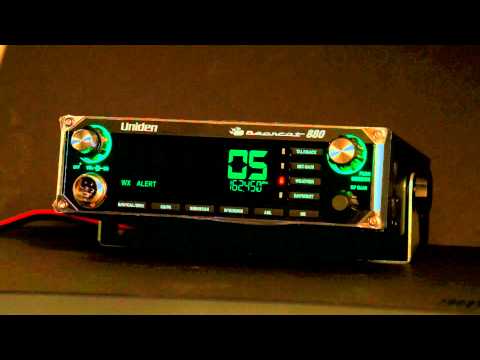
Uniden Bearcat 880
MOBILE INSTALLATION
Plan the location of the transceiver and microphone bracket before beginning installation.
1. Select a location that is convenient for operating the radio but does not interfere with the driver or passenger.
2. Install bracket with self-tapping screws provided.
3. Connect the power cords (see below).
4. Attach the microphone bracket to side of the radio or car dash.
5. Attach radio to bracket.
Mobile Antenna
Because the maximum power output of the transmitter is limited by the FCC, the quality of your antenna is very important.
To achieve the maximum transmission distance, Uniden strongly recommends that you install only a high quality antenna.
You have just purchased a superior transceiver; don’t diminish its performance by installing an inferior antenna.
Only a properly matched antenna system will allow maximum power transfer from the 50-ohm transmission line to the radiating element.
Your Uniden dealer is qualified to help you select the proper antenna for your requirements. A whip style antenna may be used for automobile installation.
A short “loaded” whip antenna is easier to install on an automobile, but its efficiency is less than that of a full quarter-wave whip antenna.
Connecting the Power Cords
Uniden recommends connecting the power lead to the Ignition Switch Accessory Terminal. This way, the transceiver is automatically turned off when the ignition switch is turned off.
As an alternative, the power cord may be connected to an available terminal on the fuse block or to a point in the wiring harness. However, caution must be taken to prevent a short circuit. If in doubt, contact your vehicle dealer for information.
Ground Information
This transceiver may be installed and used in any 12-volt DC negative ground system vehicle.
Negative Ground System
With a negative ground system, the negative (-) battery terminal is usually connected to the vehicle motor block.
Connect the red DC power cord from the transceiver to the positive (+) battery terminal or other convenient point. Then connect the black power cord to the vehicle chassis or negative (-) battery terminal.
Radio Checks
Diagnostic Menus
1. Press MENU/OK to activate the menus.
2. Turn Channel Selector until DIAG displays.
3. Press MENU/OK to enter the DIAG level.
From the DIAG level, you can check battery power levels, antenna mismatch and RF power levels.
Battery Check
Check the DC power levels if you feel your radio is not performing properly.
1. Once DIAG displays, press MENU/OK; VOLT displays.
2. Press MENU/OK; the battery voltage displays for 2 seconds and then the battery voltage condition displays:
–– PASS – Voltage is good.
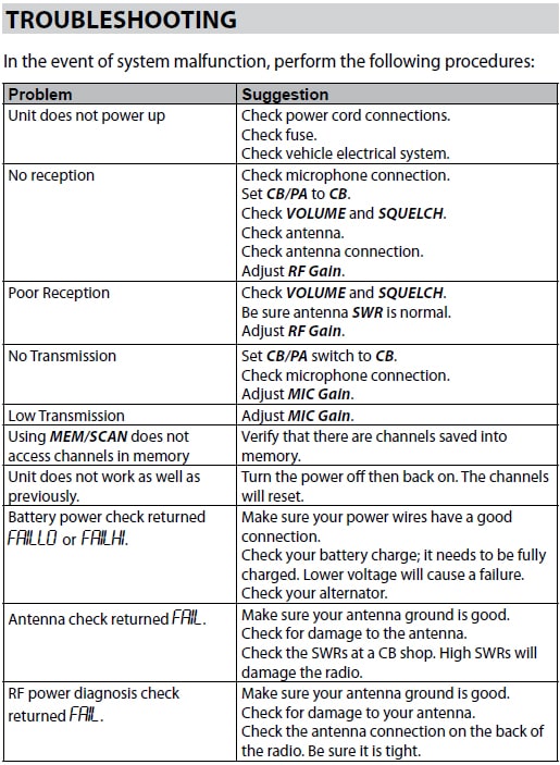
–– FAILLO – Voltage is too low.
–– FAILHI – Voltage is too high.
3. Press MENU/OK to return to the DIAG level.
Antenna Mismatch Check
An antenna mismatch indicates that reception quality may be impaired.
1. Once DIAG displays, press MENU/OK; VOLT displays.
2. Turn Channel Selector until ANT displays.
3. Press MENU/OK. GO PTT displays.
4. Press and hold PTT. The Antenna Mismatch condition, PASS or FAIL, displays.
5. Release PTT and press MENU/OK to return to the DIAG level.
RF Power Check
RF alerts indicate that the transmission levels are not acceptable.
1. Once DIAG displays, press MENU/OK; VOLT displays.
2. Turn Channel Selector until RF OUT displays.
3. Press MENU/OK. GO PTT displays.
4. Press and hold PTT. The RF power condition, PASS or FAIL, displays. (If FAIL displays, see the Troubleshooting section.)
5. Release PTT: GO PTT displays.
6. Press MENU/OK to return to the DIAG level.
S/RF/CAL/SWR Meter
You can check your incoming signal strength and output power as you use your Bearcat 880.
The 12-column LCD display (refer to item number 3 on page 5) displays this data.
Press and hold PTT on the microphone to see the RF output power levels. Release PTT to see incoming signal strength.
Calibrate Standing Wave Ratio (SWR)
Check and calibrate the SWR to ensure that you are using power effectively.
1. Press S/RF/CAL/SWR until CAL and a vertical status bar display on the LCD screen to indicate you are in Calibration mode. No bar graph status levels display.
2. Press and hold PTT; bar graphs status levels display the current level. While still holding PTT, turn Channel Selector to adjust the levels up or down.
3. Release PTT. Press S/RF/CAL/SWR until the LDC displays SWR and 1.5, 2, and 3.
4. Press PTT to see if the new calibration is between 1.5 and 2.
Repeat these steps until the calibration level is between 1.5 and 2.
Preventive Maintenance
Every six months:
1. Check the SWR.
2. Be sure all electrical connections are tight.
3. Inspect antenna coaxial cable for wear or breaks in shielding.
4. Be sure all screws and mounting hardware are tight.
Maintenance
The Bearcat 880 is designed to give you years of trouble-free service. There are no user-serviceable parts inside. It requires no maintenance
Except replacing the inline fuse in the fuse holder of the DC power cord.
To replace a blown fuse:
1. Press ends of the fuse holder together. Twist to open. Carefully separate the two pieces.
2. Remove the fuse and inspect. If blown, replace with the same type 6-amp fuse.
Note: Use only the fuse specified for your Bearcat 880. Failure to do so may void your warranty.
“How-To” Videos
Bearcat 880 Overview :

Bearcat 880 Demo Mode :